Relay Connection in DPA-1i
The DPA-1i Digital Power Analyzer features built-in relay outputs that can be configured for various control and monitoring applications. This guide explains how to properly connect and configure relays in the DPA-1i for optimal performance.
Relay Specifications
| Parameter | Value |
|---|---|
| Number of Relays | 2 (Form C contacts) |
| Contact Rating | 250V AC / 30V DC, 2A |
| Isolation | 2 kV between contacts and chassis |
| Operating Time | < 10 ms |
| Release Time | < 5 ms |
Relay Connection Diagram

The diagram above shows the typical relay connection setup in the DPA-1i. The relay contacts can be used for alarm indication, control of external devices, or automation purposes.
Relay Configuration Options
The DPA-1i relays can be configured for various functions:
- Limit Alarm: Activate when measured parameters exceed predefined limits
- Pass/Fail Indicator: Signal test results based on comparison with set criteria
- Data Logging Trigger: Start or stop data logging based on specific conditions
- External Device Control: Control external equipment based on measurement results
Setting Up Relay Parameters
- Access the Settings menu on the DPA-1i display
- Navigate to the Relay Configuration section
- Select the relay you want to configure (Relay 1 or Relay 2)
- Choose the operating mode (Alarm, Pass/Fail, etc.)
- Set the threshold values for activation
- Configure delay times if needed
- Save the settings and test the relay operation
Safety Considerations
- Ensure all power is disconnected before making relay connections
- Verify the relay contact ratings are suitable for your application
- Use appropriate wire gauge for the current levels involved
- Follow proper grounding procedures
- Test relay operation before connecting to critical equipment
Troubleshooting Common Issues
Check if the relay is properly configured in the settings menu. Verify that the triggering conditions are being met. Ensure there are no loose connections in the relay wiring.
This may occur when the measured parameter is near the relay threshold. Add hysteresis in the settings or adjust the threshold values to create a wider operating band.
Verify the relay logic settings (normally open vs. normally closed). Check if the correct measurement parameter is assigned to the relay trigger.
DPA-1i Resources
Related Products
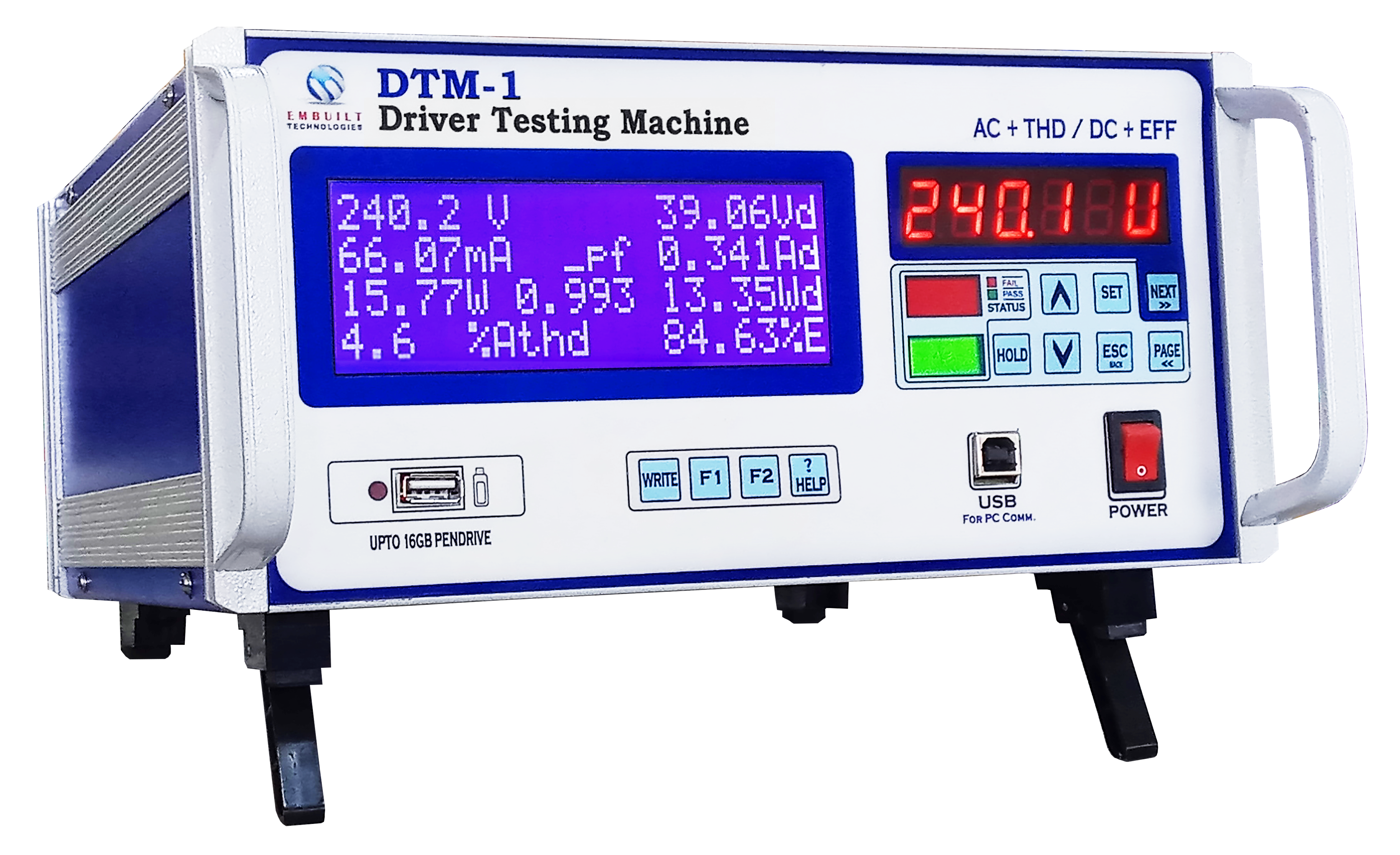
DTM-1
Digital Tester for LED Drivers
.webp)
THDPM-1
Total Harmonics Distortion Power Meter

PT-AC
Production Tester-AC